Passenger counting
For the automatic counting of the number of passengers in public transport vehicles, VLDs or trains (monitoring of vehicle occupancy) we have developed the APC (automatic people/passenger counting) system, which is designed to monitor the occupancy of individual vehicles and the subsequent creation of statistics (ADA - APC Data Analyzer software developed by us). They can be used in cooperation with on-board computers EPIS 4.0x and EPIS 5.0x or as independent systems for general public transport vehicles. In this version, they can also be installed in other applications, e.g. monitoring the number of people in a building, etc.
 The passenger counting system (vehicle occupancy monitoring) is particularly suitable for:
- Monitoring the number of passengers in the vehicle (vehicle occupancy at different times)
- Tracking of passenger load (number of passengers along the route) including many approximations
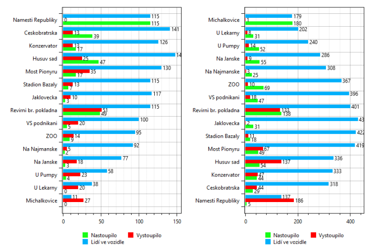
- Monitoring of bus stop load (frequency report for public transport or VLD vehicles)
- Possibly as a security camera above the door
The on-board passenger counting system (occupancy monitoring) for public passenger transport (APC) can be supplied in two variants - dependent on the EPIS PP (4.0x or 5.0x) or independent, where the necessary data for correct operation must be provided by the existing on-board computer.
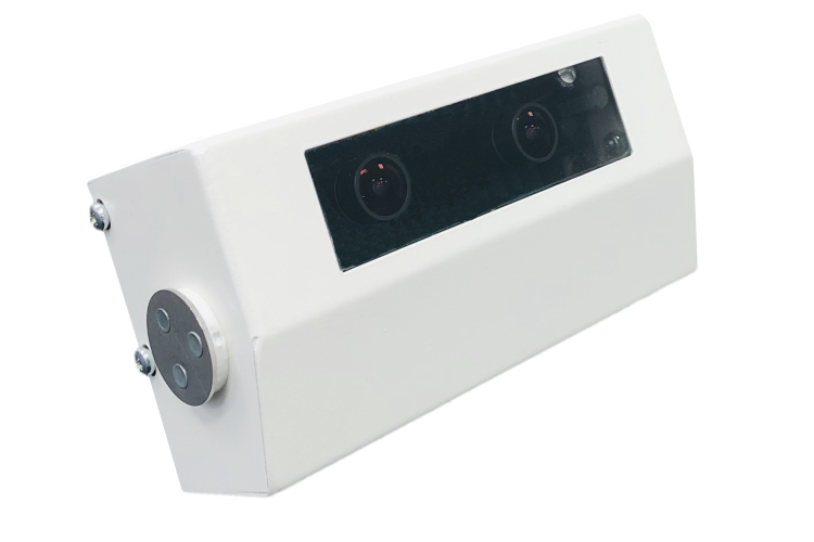
The UCP-02 units (a new more accurate type) or the earlier UCP-01 units can be used as over-the-door units. The units are SW interchangeable and use the same protocol for their control and communication.
The system is integrated into the remote playback in the vehicle. It cannot be set remotely.
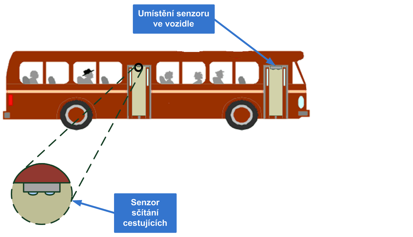
The UCP-0x occupant counting sensors themselves are designed to be mounted above the door in the interior of the vehicle, preferably in the centre of the vehicle door, with a minimum of 20 cm of clearance between the top of the head (hat) (the stereo camera must not be obscured by passengers). In this case, the highest counting accuracy is achieved. The sensors must be positioned above all doors to ensure that the measurement results correspond to reality, see the following figure. If one of the sensors fails or if the accuracy of its counting is reduced, the accuracy of the overall counting result will be reduced.
APC passenger counting system controlled by PP EPIS
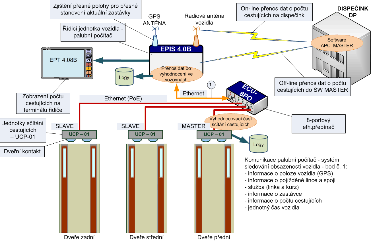 This is a system based on occupancy monitoring controlled from one of the on-board computers supplied by us for public transport vehicles EPIS 4.0x, EPIS 5FCC or MSP 5.0. Then the system consists of:
- UCP-02 (unit of people counting) or UCP-01 (production was discontinued on 10/2018), which is placed above each vehicle door (see description below),
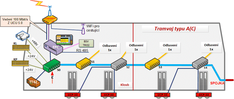
- the communication data distribution throughout the vehicle - most often an Ethernet bus is used, including a dedicated Ethernet switch, e.g. ECU-08P0 (or ECU 08P1 or ECU 08P3), which also provides direct power to the units and is controlled from the on-board computer. The use of other vehicle buses - e.g. RS 485 or CAN - must be consulted. A wiring diagram is at the end of this page.
- System counting units - i.e. applications that run on the vehicle's on-board computer - e.g. EPIS 4.0x or EPIS 50A or MSP 5.0. This application collects passenger count data from UCP-01 or now UCP-02 tracking units, stores it in a file including additional information (GPS location, stop name, times, line number, etc.). The on-board computer thus acts as a so-called datalogger and makes full use of its knowledge of the timetable and the detailed behaviour of the vehicle (thus generating very accurate data for further evaluation).
- Vehicle communication system with the dispatching centre - the on-board computer adds new data on the number of passengers to the data communication with the dispatching centre after closing the door at the stop, which the private radio network DP or GSM/GPRS/UMTS/LTE) can transmit on-line to the dispatching centre. Here, the data can already be processed by the dispatching system (e.g. SPRINTER 2019) and used to make statistics or display them to the dispatchers.
Independent APC on-board passenger counting system
The second option is a stand-alone APC system based only on passenger counting with UCP-01 or UCP-02 units, independently of the EPIS on-board computers supplied by us. In this case, it is necessary to agree on the method of connection to the on-board IT, if required, and the method of data transfer to the server where the data will be processed. The transfer can be carried out using our GSM modem of the EPG series or by enabling routing in the vehicle wiring
All processing of the captured video takes place in the UCP-01 or UCP-02 unit. Due to the intensive processing of the image data inside the unit within the multi-core processor, there is no need for an external computing unit and the data from the unit is directly transmitted to the on-board computer.
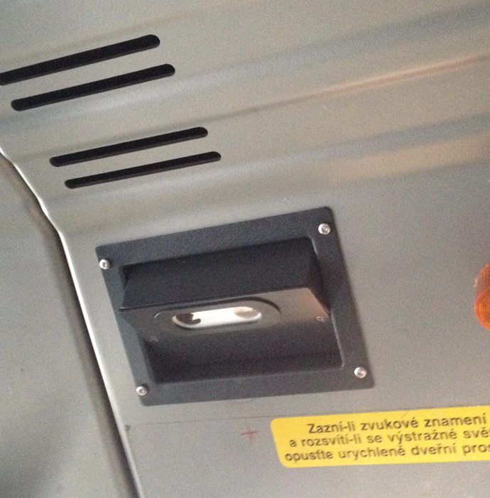
Photo of the UCP-01 unit in the vehicle - cover colour black.
Accuracy of automatic passenger counting systems
There is no standard yet for automatic passenger counting for boarding and alighting. Therefore, it is still an unclear indicator of the exact number of passengers. It therefore depends on the ambient conditions and also on the behaviour of the drivers at the final stops.
The following figure shows an example of a situation that is intractable for standard passenger counting units.
Unsolvable situation for passenger counting.
Example of the connection of an automatic passenger counting system in vehicles
Our APC units are now installed in more than 180 vehicles - the number of doors is more than 750. We use the on-board computer control to communicate with them, in conjunction with the timetable, which provides very accurate results for future evaluation.
For the wiring and power supply of the UCP-0X door units, we use PoE wiring, i.e. the EPIS on-board computer sends an instruction to the corresponding ECU-08Px unit to activate the voltage at the corresponding ECU output. This ensures that the units are only powered when the vehicle is moving with passengers and it makes sense to count them.
Wiring example of a Vario LF2R tram - the ECU 08P0 Ethernet unit (grey switch) is used to power the UCP automatic passenger counting units.
Example of T13 tram wiring - for powering the UCP units the Ethernet unit ECU 08P1 (pink switch) is used. The change in the T13 trams occurred because only the Ethernet cable is "stretched" between the cells (there is no space for IBIS) and this switch is also used as an Etherent/IBIS signal converter and vice versa.

