Island camera system

The term "island" camera system can be understood as an assembly of components providing recordings of events from vehicles or from the vicinity of vehicles on an SSD disk for later analysis of events during "some" illegal incident. "Island "in this case means that the camera system does not have a significant link to the vehicle's vehicle check-in and information system, nor is it (can be) dependent on other vehicle communications and vehicle location tracking.
Contact us
The term "island" camera system can be understood as an assembly of components providing recordings of events from vehicles or from the vicinity of vehicles on an SSD disk for later analysis of events during "some" illegal incident. "Island "in this case means that the camera system does not have a significant link to the vehicle's vehicle check-in and information system, nor is it (can be) dependent on other vehicle communications and vehicle location tracking.
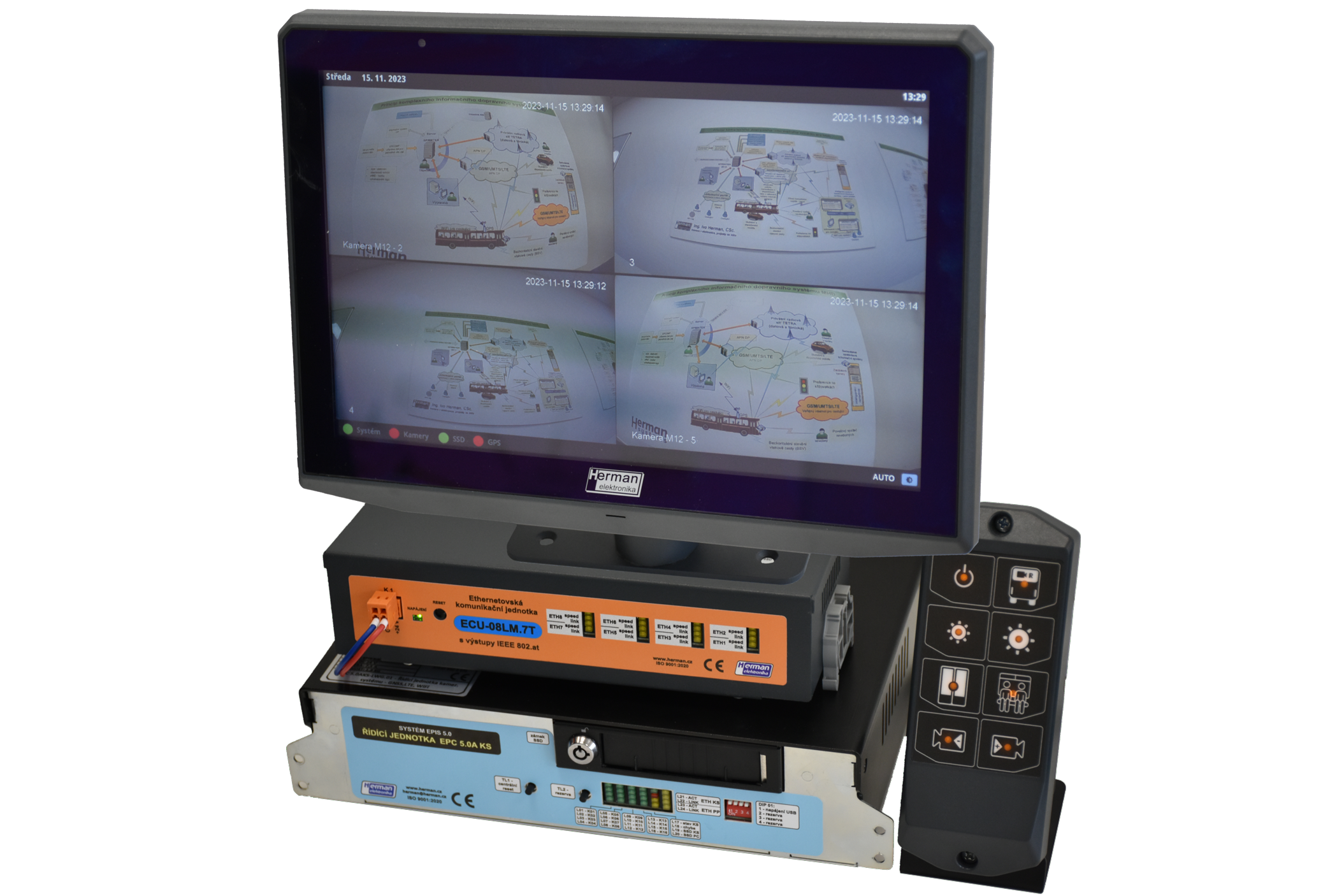
Composition of the EPIS 5.0KS in-vehicle system
In order for this independent camera system to exist, it is composed of:
- Anon-board computer of the EPIS 5.A type in the EPIS 5.0KS recording computer version with an auxiliary SSD for storing the recordings (in this 'hotswap' version). For the sake of 'independence' from on-board IT, it then includes full communication equipment such as LTE and WiFi communication and position tracking - GNSS (GPS) module. The on-board computer in the camera system version thus lives independently of the vehicle's IT and check-in status, including remote monitoring.
- LCD driverterminal designed only to monitor the events in the vehicle captured by the cameras. This terminal is not within the driver's reach and due to the simultaneous up to 4 cameras must be of the appropriate size - in our case 12.1″ (other size by agreement). In our case, it is an EPT 4.12A T01 LCD monitor, which has a standard interface like the EPIS 4.0x series on-board computer terminals. The monitor has an integrated luminance sensor for automatic brightness control and a warning LED to indicate events in the on-board computer that do not require LCD light, such as remote system updates or downloading records.
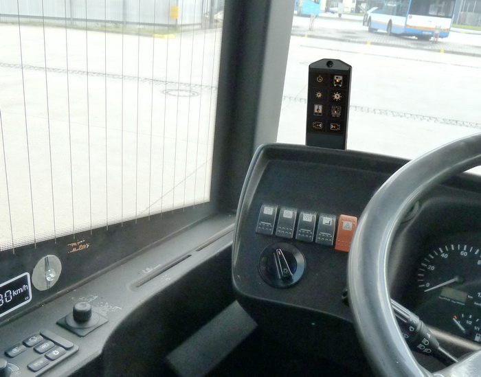 TheOV-01 control unit is designed for operator control of the camera system. This control unit was created by separating the auxiliary membrane keypad on the LCD terminals of the EPT driver on the right from the touch screen (e.g. EPT 4.10) into a separate control unit design, since the LCD terminal is located out of the driver's reach (usually up above the driver). This allows the control unit to be mounted within easy reach of the driver and allows the driver to easily operate the system.
- Vehicle cameras - are usually supplied according to the customer's requirements, including their arrangement. Their power supply is by PoE via Ethernet bus - today according to IEEE 802.11 at. This is a more powerful power supply standard with negotiation on how to turn it on.
- Wiring and Ethernet communication units (switches) - usually the cameras are connected to the appropriate ECU switch (in this case ECU 08LM.7T). The wiring can be either RJ45 or M12 type connectors - type D coding. These wiring harnesses are powered and at the same time electronically protected in the on-board computer - its EPC 5.0KS control unit.
Wiring diagram of the system in the vehicle
The following is an example of the wiring diagram of an independent (island) camera system on an articulated vehicle with 9 cameras and 2 switches (ECUs), the second one being behind the articulation (so the power supply and UTP cable are routed together through the articulation):
An example of the wiring of an independent (island) camera system in an articulated vehicle with 9 cameras.
In this case, the independent camera system is connected to the on-board computer to collect selected information for better system management - i.e. it can receive additional information from the bus about the line and destination, i.e. when searching for a tram, it can simplify the identification of the tram where the incident occurred (of particular importance in public transport, where e.g. in large junctions it can be difficult to identify the "correct" vehicle.
Conversely - the interconnection can have another positive meaning and that is fault reporting for vehicle mechanics. It is necessary to distinguish how to organize the maintenance of the system.
Working with the system from the driver's point of view
Contactless control keypad OV-01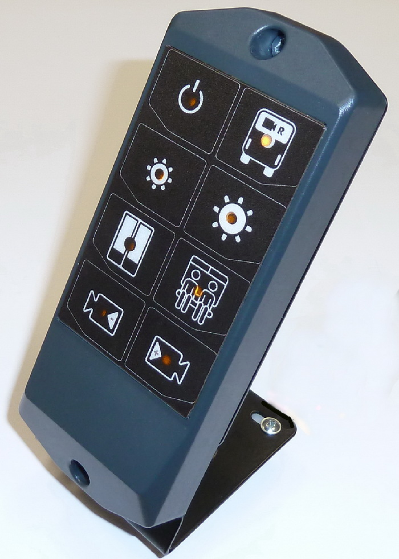
The OV-01 non-contact control sensor keypad with illuminated symbols allows easy operation of the camera display and service menu on the LCD terminal. Due to its size, it can easily be placed close to the driver's reach to select the desired functions. The keypad supports multi-touch operation with the possibility of an acoustic response to pressing the "beep" function.
The basic functions of controlling the camera system from the driver's perspective.
The driver has 8 buttons to control the independent camera system:
 Button one #1 - when manually turned off by the driver, remains off until it is turned back on or the stop or reverse camera mode is entered.
- Button No. 2 - activation of the camera monitoring movement behind the vehicle.
- Buttons 3 and 4 - control the brightness of the display with the possibility of switching to automatic/manual mode (by pressing both keys simultaneously - displayed on the LCD)
- Button 5 - switches the display to door display automatically when the door is opened. Manually the option can be changed.
- Button No. 6 - pressing it switches the display to the interior camera layout last used, then pressing it changes the layout.
- Button 7 and 8 - Scroll forward and backward through the individual cameras.
Opening the door activates the stop mode, closing the door activates the drive mode, or switches off according to the driver's previous settings. The reversing camera can be displayed automatically after reversing, depending on the configuration and the information in the system.
Display unit EPT 4.12A T01
The display device (LCD monitor) is intended to be placed in the driver's cab in the driver's field of vision as far as possible so that it does not obstruct the view from the driver's seat and does not interfere with driving. The monitor may be divided into an appropriate number of agreed parts displaying online images from individual cameras in the required number and as large as possible. The layout of the images of the individual cameras on the monitor is user adjustable.
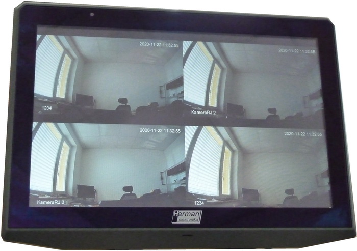
EPT 4.12A T01 in the function of a vehicle camera display.
The monitor allows the brightness to be adjusted either automatically or manually by the driver. Includes an indicator LED to indicate system operation (data download) for quick review when the LCD is turned off.
With a simple toggle, the status of all system components, the reversing camera display or the view behind the car can be displayed completely. The monitor can also be switched off and on by the driver and is always activated when entering a stop.
Control unit (recording device) - EPC 5.0A KS
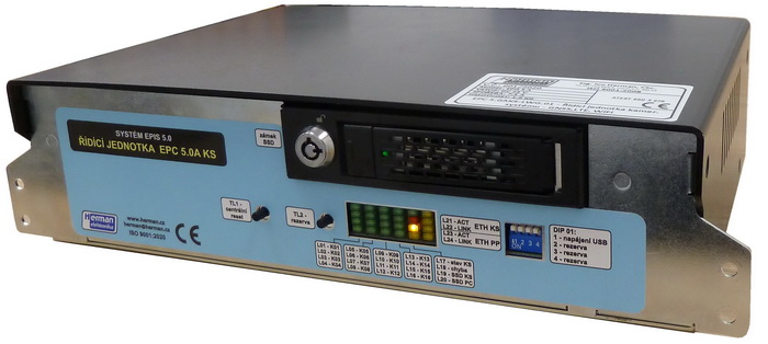 The control unit (recording device) - type EPIS 5.0A KS is based on a powerful PC with an SSD drive for the OS and is supplemented by a large-capacity removable SSD drive for recording camera signals. The unit has an interface to the driver's LCD terminal. It includes a backup battery to ensure "catch-up" of camera footage in the event of an accident or to bridge power outages without damaging operations.
Wi-Fi, GNSS, LTE modules are included in the control unit and one multi-antenna is connected to them. The status of the cameras is indicated by the LED on the front of the EPC. Its use is also suitable for double-sided trams.
Ethernet switch ECU 08LM.7T
This is an Ethernet bus unit with 8 ports (switch) with 7x PoE output with negotiation according to IEEE 802.3at standard. These PoE outputs are primarily intended for powering in-vehicle cameras.
This ECU switch has mechanical dimensions due to the use of mechanically sized M12 connectors.
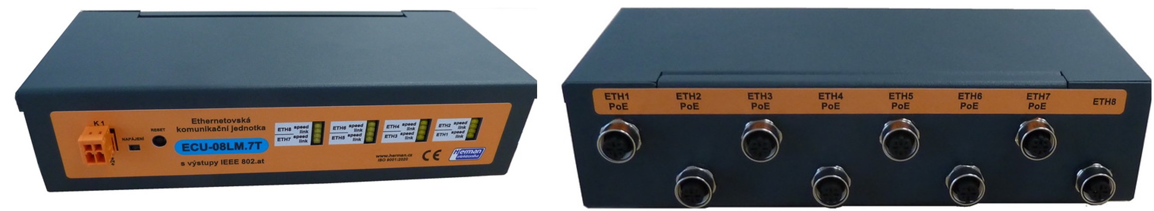
ECU Ethernet Switch 08LM.7T
Working with the system from the service technician's point of view
From the service technician's point of view, the camera signal provides basic diagnostic information both directly on the vehicle and on the BOS-KS monitoring server (see below). It can be called up on the vehicle simply by pressing the multi-touch keypad. There are the following diagnostic windows:
- Describing the status of the camera system, including recording and established communication with individual cameras.
- Status of communications with the surrounding area
- Checking the definition of views directly in the vehicle (sent via BOS-KS)
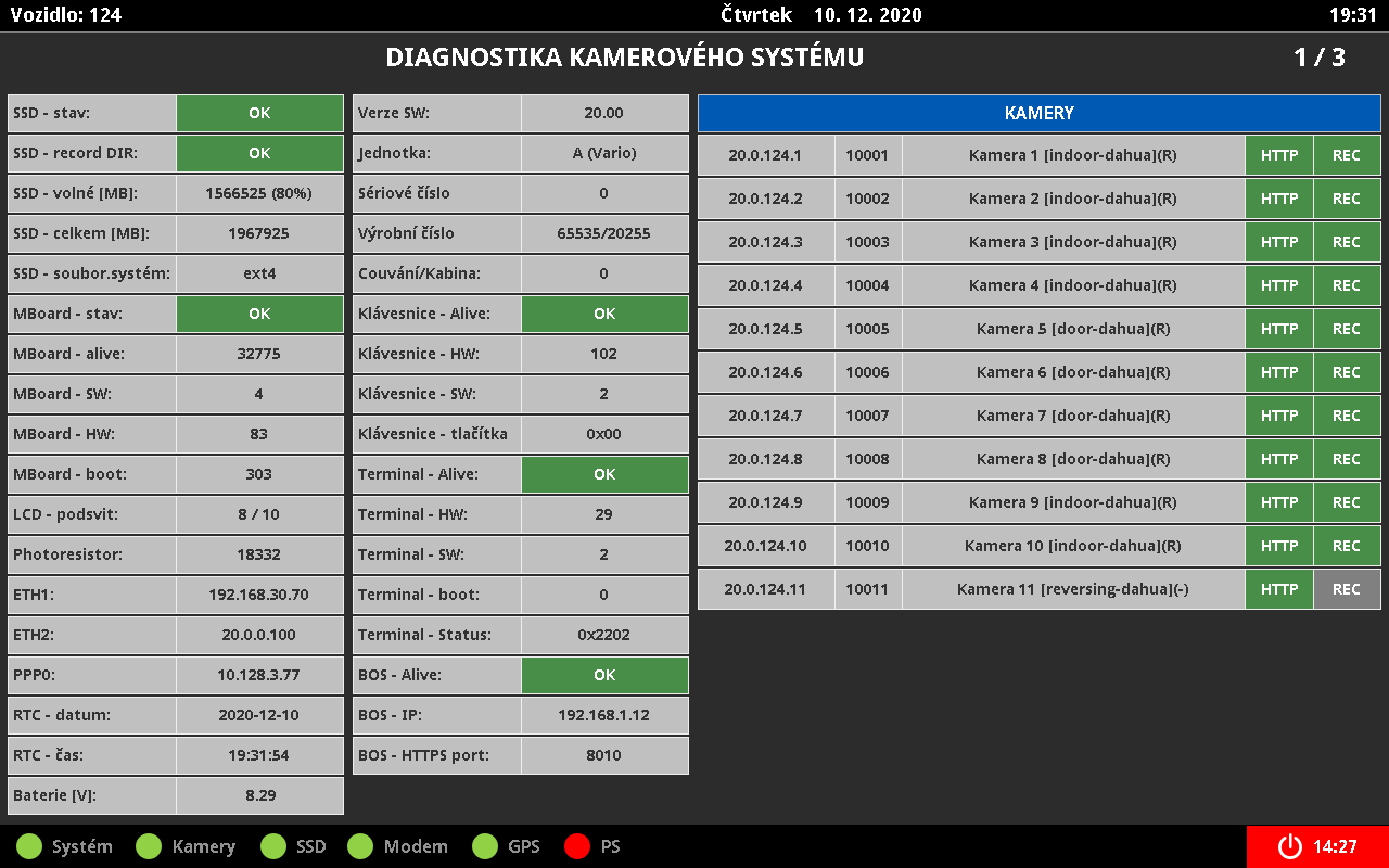
The main diagnostic window of the cameras and the recording on the SSD and the status of the on-board computer controller EPC.
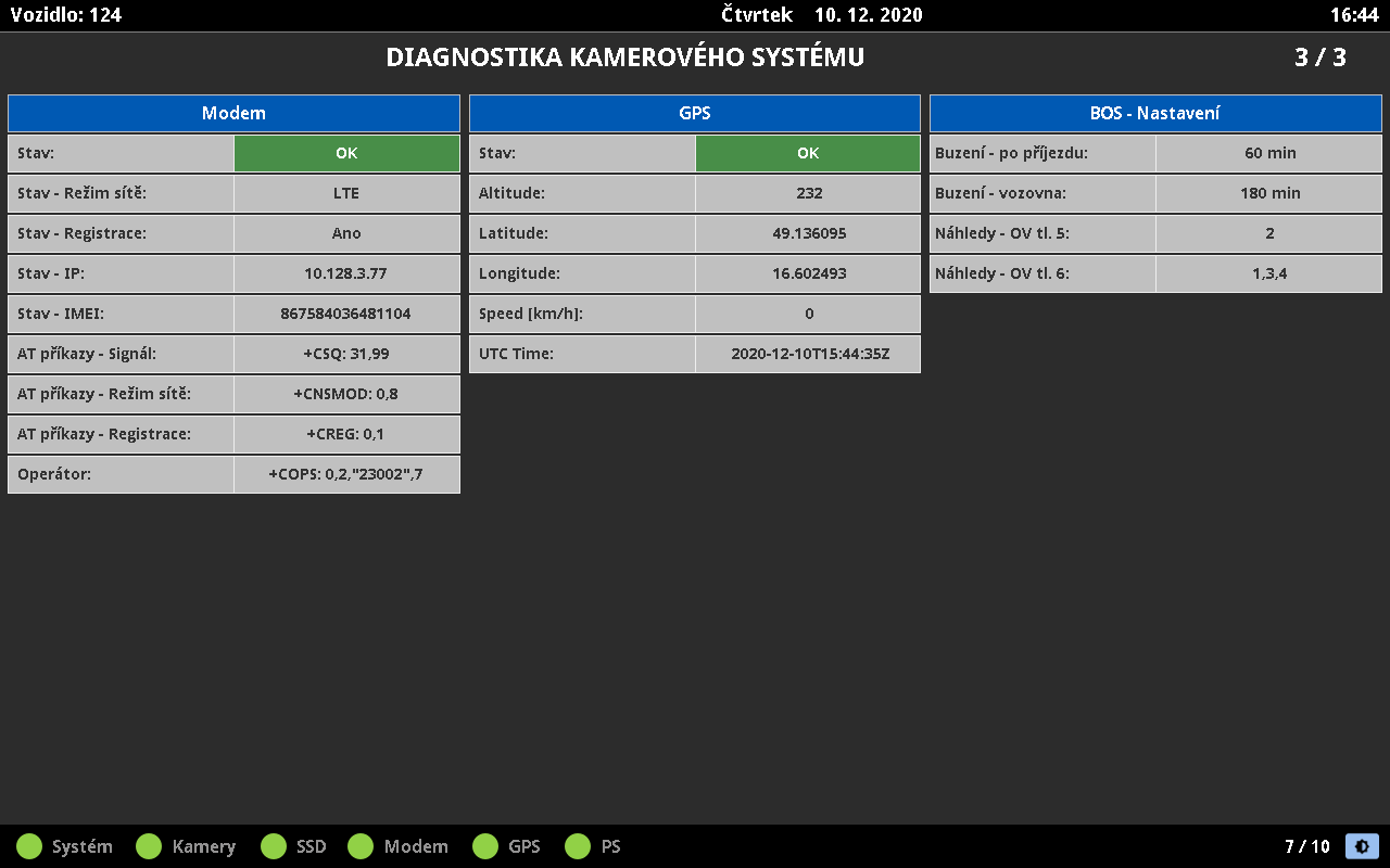 Diagnostic window for LTE communication, GNSS unit and communication to the surveillance server
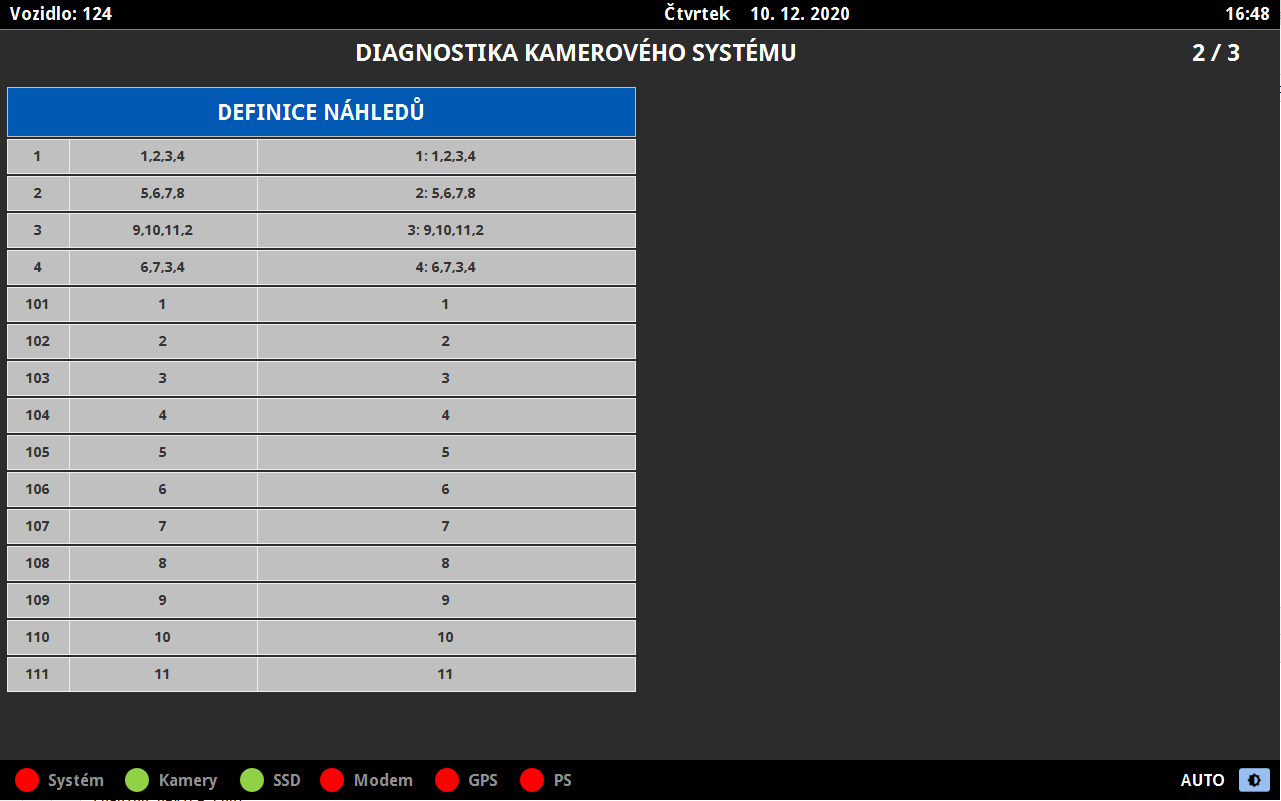
View definition views - is transmitted to the unit from the surveillance server.
The bottom bar then displays the status of the system, cameras according to the sent configuration, recording SSD, LTE modem, GPS (GNSS) and communication with the on-board system. On the right is the symbol of the LCD terminal brightness setting (in this case it is automatic). This symbol can be mistaken for the vehicle shutdown symbol if the signal from the vehicle start (start or key) is "dropped".
Surveillance software over the camera system
The central software for the management of the camera system is KS-BOS, which is a client-server type and allows the operator to remotely supervise the entire system. It enables on-line and off-line communication with thousands of vehicles and their systems. Through the BOS API it is possible to connect individual functionalities with other systems of the user, to generate statistics on the status of vehicles, to solve reports for the Helpdesk, etc.
Communication of BOS software with vehicles:
- On-line communication: the status of cameras and other system components, including their settings, are sent on-line to the server every 30 seconds and vice versa, and can be completely controlled from there,
- Off-line communication: reading of camera footage via Wi-Fi connection in the vehicle bays.
The principle of the KS-BOS monitoring and control software:
The principle of the KS-BOS monitoring and control software
Server functions:
- Remote software update or remote setting of system and vehicle parameters
- Video management - downloading, decryption and viewing of recordings
- Video downloading - selection of vehicles, individual cameras and selection of download type (WiFi/LTE)
- Setting vehicle properties (creating vehicle models, setting individual components, setting individual screens to individual button presses
- Managing user permissions and roles
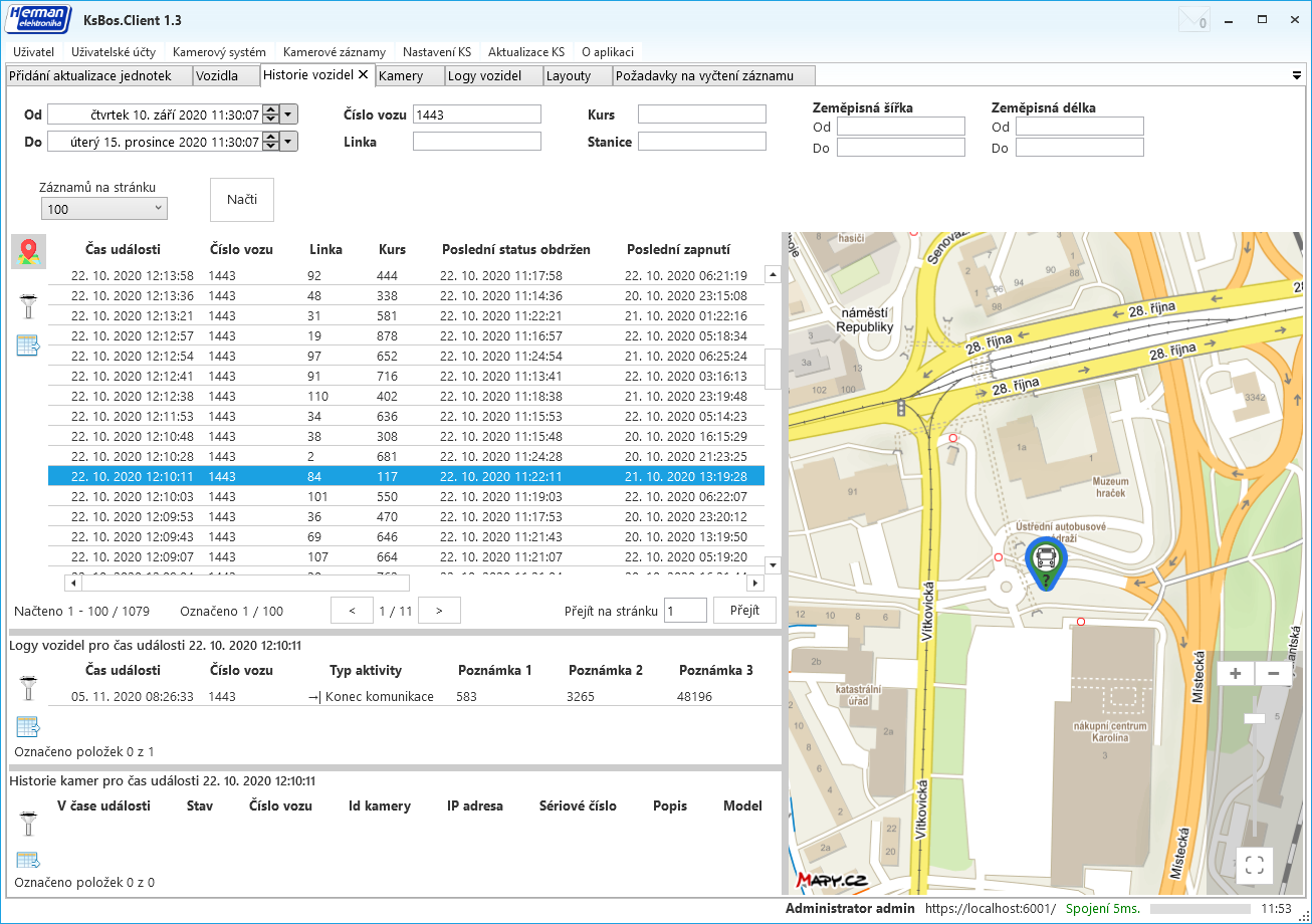
- Vehicle history and logs - checking on, off and functional status, checking movement over the map
Demonstration of how to work with the history status of camera systems:
 Window "Adding a request to read logs" in KS-BOS
Window "Vehicle history" in KS-BOS