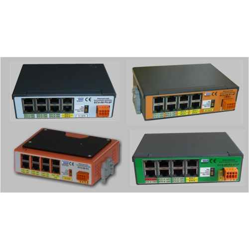
Ethernet Control Units (ECUs)

The use of ECU communication units is mainly in vehicles where they provide the distribution of the Ethernet bus throughout the vehicle (they have a power supply of +12V to +24V). For controlled PoE outputs, they have a special communication protocol for switching them on/off from a higher-level unit (on-board computer - e.g. EPIS 4.0x or EPIS 5.0Ax). They are also suitable for powering cameras or other in-vehicle devices (+48V or -48V) or can be used as an Ethernet/IBIS converter.
Method of marking the communication units
The ECUs are newly marked as follows from 1.4.2018 and from 10.2.2021 onwards and are based on the ECU classification - XY.Z-T (they refine the previous marking by refining it according to the variant of the solution). The meanings are:
- Where X is the number of communication ports of the unit. Currently the number of communication ports is 4/5/8 - the X designation is then 04/05/08 - and is indicated in the unit name.
- Where Y denotes details of the unit, in particular the ability to power the connected device:
- L - "light" - a simplified version of the unit without the possibility of power supply via POE - the so-called unmanaged switch,
- LM - "light with M12 connectors" - like the L version but outputs via M12 connector - type D coding (other on request)
- P - "processor" - with the ability to controllably power connected devices over an Ethernet cable. The units are manufactured with different numbers of communication ports and differ only in the number of ports and dimensions. The internal layout and connectivity of the units do not differ. The PoE voltage is derived from the power supply voltage.
- Where xZ refines the unit type according to the number and design of PoE.
a) For the PoE design:
- Version xE has the meaning of power supply type B according to the PoE standard - a simplified version that allows external PoE to be transmitted between inputs 1 and 2 (ECU 05L.2E units) or between inputs 1, 2 and 3 (ECU 05L.3E unit), i.e. if external PoE power arrives after one input, it is connected to the other inputs.
- Version xN - denotes the number of uncontrolled PoE type B, where the output is +12V supply voltage.
- Version xP - denotes the number of uncontrolled Type B PoE, where the output is directly the vehicle supply voltage (+24V for public transport). The ECU 05L.1P version with one output or the ECU 05L.2P version with two outputs are available.
- Version xL - the same as xP, but the power supply is not switched by the processor and electronic fuse, but is implemented via a reversible electronic fuse (valid from 10.2.2021).
- Version xF - denotes the number of unmanaged PoE type F according to the IEEE 802.3 af standard including output power negotiation. For example, ECU 08L.1F is produced, i.e. with one 48V PoE power output - the version is type B (no power output refinement after F).
- Version xFa - loads a number of unmanaged PoE type F according to the IEEE 802.3 af standard including output power negotiation. The PoE type implementation is Type A .
- Version xT - indicates the number of uncontrolled Type T PoE according to the IEEE 802.3 at standard including output power negotiation. For example, the ECU 08LM.7T is produced, i.e. with seven outputs with PoE -48V power supply and power outputs from 50W to 200W or the ECU 08L.+7T with seven outputs with +48V power supply.
- Version xV - denotes the number of uncontrolled passive PoE type B, where the output is +48V supply voltage, with each output having its own electronic fuse.
b) For the design in terms of internal layout:
- Version 0.xP - denotes a version that provides up to 7 outputs with an electronic switched fuse and short circuit indication including output voltage measurement. It can be supplied from 1 PoE output up to 7 PoE type B outputs - e.g. ECU 08P0.6P is produced.
- Version 1.xP - same as version 0, but additionally includes IBIS bus output. It is produced in the ECU 08P1.2P version.
- Version 2.xV - with the possibility to supply the connected device via eth. cable with +48V. This is generated from the supply voltage by a voltage converter. It is produced in the ECU 08P2.4V to ECU 08P2.7V version according to the number of switches installed.
- Version 3.xFxP - this is a combined version of the output power supplies functionally identical to the version with 0, but the switch also includes PoE type IEEE 802.3 af. It is manufactured in ECU 08P3.1F5P.
- Where T denotes the mechanical mounting design of the communication unit:
- H - denotes the horizontal mounting method (standard design).
- V - indicates vertical mounting (to be specified in the order).
General characteristics of communication units for Ethernet
Today we produce the 2nd generation of communication units for Ethernet bus. There are two basic types of ECU communication units - five-port and eight-port, which are ready for the use of additional functions and are designed especially for public or regional public passenger transport vehicles (they have the approval of the Railway Authority) and SD8 Atest.
The ECUs can be controlled by a processor and can also implement some auxiliary functions such as:
- control of the PoE (Power over Ethernet) interface with +24V/+12V,
- Serial lines and single-bit I/Os can be connected (extension of functions on request),
- PoE interface control (newly ECU 08P2) then meets IEEE 802.3af type B standard - i.e. +48V power supply.
The production of the four-port version of the switch has been cancelled, it is replaced by the backward compatible version ECU 05x.
ECU-0x communication units can perform 3. different basic functions (depending on the PCB mounting):
- Simple unmanaged Ethernet switch - 5 or 8 port.
- Unmanaged Ethernet switch function with PoE controlled (PoE output standard +12V / +24V / +48V and TPoE) by processor.
- Ethernet switch in the function of IJN (integrated power unit) designed also for vehicle power management with the possibility to add e.g. GSM/GPRS/UMTS/LTE modem or other module.
The basic features of communication units as Ethernet bus switches are:
- Non-blocked switching architecture forwards and filters packets at full cable speed to ensure maximum throughput.
- Automatic detection of incorrect cable.
- Auto MDI/MDIX feature eliminates the need for crossed cables.
- Meets IEEE 802.3, 10/100M full/half-duplex, supports IEEE 802.1 priority system.
- Throughput up to 2 Gbps, 64/128 kbytes SRAM per data, 1000 MAC addresses.
- Full-duplex or half-duplex data flow control.
- Feature set for VLAN, QoS management, MIB.
- Power supply 9 - 32V (not valid for switches with PoE higher than +24V).
- Wide operating temperature range of -30 to 70°C.
- IP 30.
- Meet EMC requirements per EN 50498, article 7.1. and 7.2. and ISO 7637-2:2004.
- DIN rail mounting in the "lying flat" position.