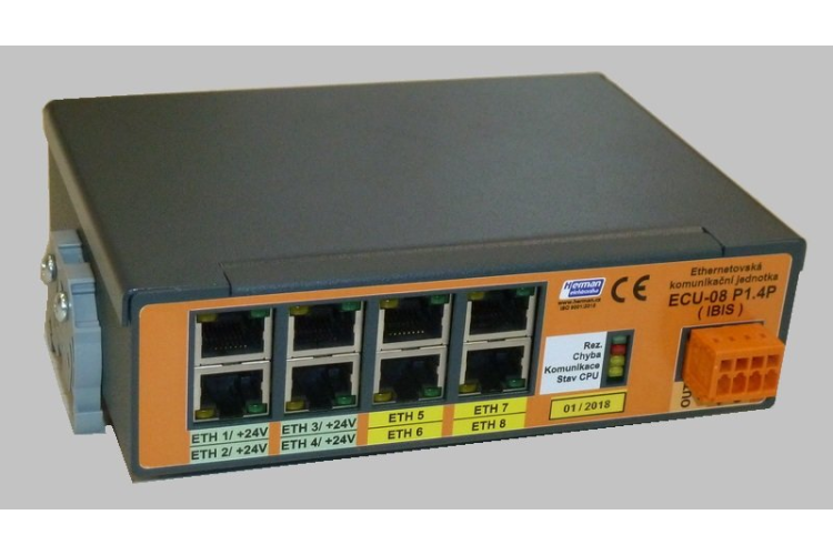
Ethernet switch ECU-08P1
The ECU-8P1.xP is a vehicle Ethernet communication unit that allows up to 6x passive PoE type B output including intelligent control from a higher-level unit (on-board computer). Its main function is the conversion of commands sent over the Ethernet bus and its conversion to the IBIS bus for places where it is not possible to transmit data simultaneously over the IBIS bus and the Ethernet bus (e.g. couplers in trams, within the joint transitions in T13 trams).
Contact us
The ECU-8P1.xP is a vehicle Ethernet communication unit that allows up to 6x passive PoE type B output including intelligent control from a higher-level unit (on-board computer). Its main function is the conversion of commands sent over the Ethernet bus and its conversion to the IBIS bus for places where it is not possible to transmit data simultaneously over the IBIS bus and the Ethernet bus (e.g. couplers in trams, within the joint transitions in T13 trams).
These Ethernet switches are intended for use within RIS II for use in trams:
- T13 in the individual links of a tram acting as a front car - in this case addressing is done on a link by link basis - see vehicle description for a more detailed description.
- T3 and T6 behave as a control unit in a rear car type B, where the "Rear car" pin is set and the other pins are set to value. Thus, for a B car, it must have address 0 - the main switch.
Example of switch wiring in a rear car where Ethernet and IBIS can be distributed at the same time.
ECU-8P1.xP function:
Simple uncontrolled switch - 8 ports with high throughput (see general parameters).
- PoE outputs power management function - up to 6x PoE 24 V / 0.7 A per output with electronic fuse.
- Switch in the function of an integrated IJN power supply unit - the on-board computer uses commands to switch on those power supplies that are specified in the vehicle configuration.
- The switch can be switched on via PoE type B (power supply must be separate).
- The ECU-08P1.xP switch has an integrated IBIS (IPIS) interface identical in HW to the EPIS 4.0x on-board computer (see description of the IBIS bus in the on-board computer). The unit serves as a bidirectional Ethernet/IBIS converter.
- Auxiliary output and input can be enabled on the front connector.
- Function indication:
- Yellow lower LED flashes when the CPU is working,
- yellow middle LED flashes when communicating with the parent system,
- red - indicates an error in the unit
The basic feature of the communication unit as an Ethernet bus type switch is:
- Non-blocked switching architecture forwards and filters packets at full cable speed to ensure maximum throughput.
- Automatic detection of incorrect cable.
- Auto MDI/MDIX feature eliminates the need for crossed cables.
- Throughput up to 2 Gbps.
- Full duplex or half duplex flow control.
- Feature set for VLAN, QoS management, MIB.


